2011/09/05更新:
利用這一年當兵放假的時間,有空就東摸摸西摸摸,一開始只是插麵包版,但是卻不知道什麼原因一直沒辦法燒錄,最後氣到了直接焊上去,沒想到...可以燒錄了! 至於是啥原因就不再管他了。
正面

背面

-----------------------------------------------------------------------------------------------------
Atmel 89 Series Device Programmer(Atmel 89系列的燒錄器)
Powerful programmer for the Atmel 89 series of microcontrollers that includes 89C51/52/55, 89S51/52/55 and many more. With this article you can make your own programmer. This is a complete programming solution when it is attached to a suitable power supply and connected to your personal computer. Proload and Firmware Version 4.1 at 57600 speed.
 Features
* Supports major Atmel 89 series devices
* Auto Identify connected hardware and devices
* Error checking and verification in-built
* Lock of programs in chip supported to prevent program copying
* 20 and 40 pin ZIF socket on-board
* Auto Erase before writing and Auto Verify after writing
* Informative status bar and access to latest programmed file
* Simple and Easy to use
* Works on 57600 speed
Specifications
Dimensions: 76mm x 180mm (3" x 7")
Power Supply: 14-18V DC or 12-16V AC
Interface: RS-232, 9-pin D connector
Data Speed: 57600 bps, 8 bits, no parity, 1 stop, no flow control
File format: Intel 8-bit HEX
Program Sockets: 40 pin DIP - 0.6" & 20 pin DIP 0.3" ZIF socket
Software: Works on Windows 95, 98, Me, 2000, NT, XP
Introduction
Simple to use & low cost, yet powerful flash microcontroller programmer for the Atmel 89 series. It will Program, Read and Verify Code Data, Write Lock Bits, Erase and Blank Check. All fuse and lock bits are programmable. This programmer has intelligent onboard firmware and connects to the serial port. It can be used with any type of computer and requires no special hardware. All that is needed is a serial communication port which all computers have.
All devices have signature bytes that the programmer reads to automatically identify the chip. No need to select the device type, just plug it in and go! All devices also have a number of lock bits to provide various levels of software and programming protection. These lock bits are fully programmable using this programmer. Lock bits are useful to protect the progam to be read back from microcontroller only allowing erase to reprogram the microcontroller.
The programmer connects to a host computer using a standard RS232 serial port. All the programming 'intelligence' is built into the programmer so you do not need any special hardware to run it. Programmer comes with window based software for easy programming of the devices.
 Supported Devices
The table below shows the key differences between the various microcontrollers. Data sheets for each device can be found on the Atmel web site. All these devices are supported by the programmer.
| Flash (Kbytes) | EEPROM | RAM (Bytes) | I/O Pins |
| AT89C51 | 4 | | 128 | 32 |
| AT89LV51 | 4 | | 128 | 32 |
| AT89C52 | 8 | | 256 | 32 |
| AT89LV52 | 8 | | 256 | 32 |
| AT8C55 | 20 | | 256 | 32 |
| AT89LV55 | 20 | | 256 | 32 |
| AT89S51 | 4 | | 128 | 32 |
| AT89LS51 | 4 | | 128 | 32 |
| AT89S52 | 8 | | 256 | 32 |
| AT89LS52 | 8 | | 256 | 32 |
| AT89S53 | 12 | | 256 | 32 |
| AT89LS53 | 12 | | 256 | 32 |
| AT89S8252 | 8 | 2 Kb | 256 | 32 |
| AT89LS8252 | 8 | 2 Kb | 256 | 32 |
| AT89C1051 | 1 | | 128 | 15 |
| AT89C2051 | 2 | | 128 | 15 |
| AT89C4051 | 4 | | 128 | 15 |
These microcontrollers from Atmel use flash memory to store programs. Flash memory can be electronically erased and programmed, no need for a UV eraser.
Hardware
Major parts of this programmer are Serial Port, Power Supply and Firmware microcontroller.
Serial data is sent and received from 9 pin connector and converted to/from TTL logic/RS232 signal levels by MAX232 chip. A Male to Female serial port cable, connects to the 9 pin connector of hardware and another side connects to back of computer. Serial Cable is made with 9 pin male connector to 9 pin female connector and connect pins 2,3 and 5 straight.
Power supply is attached to DC Socket, The bridge rectifies and make the polarity proper, This voltage is unregulated called VDD. From VDD the required supply are generated on board.
Hardware's central part is the firmware that makes the programmer intelligent. Firmware of this programmer is responsible to recognize inserted chip in either of the two ZIF socket. This information is sent to ProLoad on the computer. When a hex file is sent from the computer, the target MCU is loaded with appropriate address, data and control signals. After the programming of all data is finished the data written is sent to computer for verification.
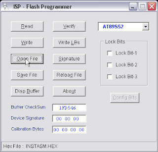
Programming Software
Computer side software called 'ProLoad V4.1' is executed that accepts the Intel HEX format file generated from compiler to be sent to target microcontroller. It auto detects the hardware connected to the serial port. It also auto detects the chip inserted and bytes used. Software is developed in Delphi 7 and requires no overhead of any external DLL.

Connects to your computer's serial port (Comm 1, 2, 3 or 4) with a standard DB9 Male to DB9 Female cable. (Cable Included). Baud Rate - 57600,COMx Automatically selected by window software. No PC Card Required. Uses Intel Hex Data Format (Default output of most assemblers and compilers.)
Download
*
Schematic
*
Proload 4.1
*
Hex file
*
BOM
*
PCB (pdf)
Forum for people who are facing problems with 89 series programmer is at
http://www.sunrom.com/forum/
***************************************************************************
電路圖資料


